Technical White Paper: RealMeter Calibrated Leak Standards: Full-Spectrum RGA Applications in the Semiconductor IndustryRealMeter Calibrated Leak Standards: Full-Spectrum RGA Applications in the Semiconductor Industry
RealMeter Calibrated Leak Standards: Full-Spectrum RGA Applications in the Semiconductor IndustryTechnical White Paper: RealMeter Calibrated Leak Standards: Full-Spectrum RGA Applications in the Semiconductor Industry
睿米标准漏孔在半导体 RGA分析全场景应用
RealMeter Calibrated Leak Standards: Full-Spectrum RGA Applications in the Semiconductor Industry
Technical White Paper
RealMeter Calibrated Leak Standards:
Full-Spectrum RGA Applications in
the Semiconductor Industry
From HHC Semi-Quantitative Monitoring to Absolute Quantitative Metrology
Using C12 N-Dodecane as the Core Anchor
RealMeter Instruments Co., Ltd. (Shanghai)
2026
Executive Summary
As semiconductor advanced processes evolve toward the 7 nm node and below, the sensitivity to Hydrocarbon Compound (HHC) contamination in EUV lithography, high-selectivity etching, and other critical processes has increased dramatically. EUV photon energy reaches 92 eV, sufficient to break C-H (~4.3 eV) and C-C (~3.6 eV) bonds and initiate carbon deposition. A carbon layer growth of merely 0.1 nm can affect Critical Dimension (CD) control. However, current mainstream HHC monitoring approaches in the industry -- ellipsometry-based result inspection, Hydrogen Radical Cleaning (HRC) as post-event remediation, and RGA threshold alarming -- are all "black-box" semi-quantitative methods lacking process-oriented absolute quantitative capability.
This white paper proposes RMI-C12 (n-dodecane, C$_{12}$H$_{26}$) Calibrated Leak Standards as the core anchor to enable Residual Gas Analyzers (RGA) to transition from "semi-qualitative trend monitoring" to "absolute quantitative metrology." N-dodecane exhibits a moderate vapor pressure of ~13 Pa at 23 degrees C. Through single-channel capillary molecular-flow restriction, it delivers stable leak rates in the $10^{-10}$ to $10^{-5}$ Pa.m$^3$/s range with calibration uncertainty of plus or minus 5%. Once the RGA response factor is established via C12 calibration, arbitrary RGA readings can be converted to absolute flux units such as molecules/cm$^2$.s, enabling cross-tool and cross-factory data comparability.
Key Findings
Current semiconductor HHC monitoring operates in a "black-box" mode: ellipsometry inspects results, HRC performs remediation, and RGA only alarms -- lacking process-oriented absolute quantification.
C12 Calibrated Leak Standards provide a known leak rate $Q$ (Pa.m$^3$/s); RGA measures response $I$ (A). Once the response factor $RF = I/Q$ is established, RGA readings can be directly converted to absolute flux.
C12 Calibrated Leak Standards cover 9 core application scenarios in semiconductor manufacturing, from EUV "absolute quantification plus predictive control" to DUV "standardized calibration plus batch management."
The RealMeter liquid-phase calibrated leak product family uses C12 as the core anchor, complemented by PFTBA (full-range calibration gold standard) and H$_2$O (water vapor quantification), enabling precise quantitative calibration of RGA for HHC and carbon contamination.
The technology has achieved hundred-unit-scale procurement and deployment across DUV, EUV, CVD, and etch platforms, entering the scaled-deployment phase.
Temperature Sensitivity Note
The C12 leak rate temperature coefficient is approximately 12%/degree C, significantly higher than permeation-type He leaks (~4%/degree C) and microchannel leaks (0.1%/degree C). Precision applications are advised to integrate temperature control modules (plus or minus 0.1 degree C) or develop temperature compensation algorithms.
Chapter 1 Technical Background: The HHC Contamination Crisis in Advanced Processes
1.1 EUV Lithography and Hydrocarbon Contamination
Extreme Ultraviolet (EUV) Lithography is the core technology enabling 7 nm and below advanced process nodes. The EUV light source wavelength is 13.5 nm, corresponding to a photon energy of approximately 92 eV -- far exceeding the bond energies of C-H (~4.3 eV) and C-C (~3.6 eV) in hydrocarbon compounds. When EUV photons strike hydrocarbon compounds (HHC) present in the vacuum chamber, they can initiate photochemical reactions that lead to carbon deposition on optical surfaces.
EUV lithography systems employ Mo/Si multilayer mirror structures, whose reflectivity is extremely sensitive to surface carbon contamination. Studies have shown that a carbon layer growth of merely 0.1 nm can cause significant reflectivity degradation, thereby affecting exposure dose uniformity and Critical Dimension (CD) control. In high-volume manufacturing environments, HHC contamination has become one of the significant sources of EUV lithography yield loss.
Major sources of HHC include:
Photoresist outgassing: Organic solvents and resins in photoresist continuously release hydrocarbon vapors in vacuum environments.
Vacuum sealing materials: Outgassing from O-rings, lubricating greases, and other elastomeric materials.
Process gas residuals: Organic precursor residues from preceding process steps.
Maintenance-induced contamination: Contaminants introduced by human hands, tools, and cleaning agents during maintenance operations.
1.2 The "Black Box" Dilemma of Current Monitoring Methods
The semiconductor industry currently relies on three primary methods for HHC contamination monitoring, each with fundamental limitations:
Comparison of Current HHC Monitoring Methods
Monitoring Method
Operating Principle
Output
Fundamental Limitation
Ellipsometer
Polarized light measures carbon film thickness
Carbon thickness (nm)
Result-oriented -- carbon has already deposited, no prevention possible
Semi-quantitative -- cannot convert to absolute flux
The common characteristic of these three methods is their "black-box" nature -- they each reflect the HHC problem from different angles but cannot establish a complete causal chain from "chamber hydrocarbon flux to carbon deposition rate to yield impact." The industry urgently needs a technology capable of absolutely quantifying HHC flux, enabling a paradigm shift from "result monitoring" to "process prevention."
1.3 Industry Pain Point: From Qualitative to Absolute Quantitative
Semiconductor manufacturing is entering a new stage requiring "absolute quantification." The following scenarios highlight the inadequacy of current technological capabilities:
EUV Process Window Definition: A quantitative model of the form "X molecules/cm$^2$.s of HHC flux causes Y nm/hour of carbon deposition rate" is needed, yet current RGA systems can only provide arbitrary units.
Cross-Tool Process Consistency: Within the same fab, different EUV tools have RGA systems from different brands, models, and calibration states, making readings incomparable -- "RGA reading of 500 on Tool A" and "RGA reading of 500 on Tool B" may represent completely different physical realities.
Photoresist Batch Management: Screening of new photoresist batches before fab entry requires absolute-dimension qualified standards, not relative trends.
Domestic Equipment Substitution Verification: Domestic equipment manufacturers need quantifiable HHC control metrics to demonstrate "equivalent or even superior" performance when replacing imported equipment.
Core Insight
The common requirement across all these needs is an HHC standard source traceable to the SI unit system, for calibrating RGA and establishing an absolute response factor. RMI-C12 Calibrated Leak Standards are designed precisely to meet this need. They provide a known leak rate $Q$ (Pa.m$^3$/s); the RGA measures response $I$ (A). Once the response factor $RF = I/Q$ is established, RGA readings can be directly converted to absolute flux -- a technological leap from "seeing a peak" to "knowing exactly how much."
The RealMeter Calibrated Leak Standards product portfolio is designed around the full-spectrum needs of semiconductor RGA calibration, employing RMI-MTC micro-channel capillary technology and RMI-Metal metal sealing technology, complemented by PSOZV/MDZV zero-dead-volume valve systems. This chapter provides an overview of the product landscape, with subsequent chapters providing in-depth analysis.
2.1 Gaseous and Mixture Calibrated Leak Standards
RealMeter Gaseous and Mixture Calibrated Leak Standards Product Overview
Category
Supported Gases/Components
Typical Leak Rate Range
Primary Applications
Inert gases
He, Ne, Ar, Kr, Xe
$10^{-3}$ to $10^{-10}$ mbar.L/s
He leak detection calibration, vacuum baseline calibration
Reactive gases
H$_2$, D$_2$, O$_2$, N$_2$, CO, CO$_2$
$10^{-3}$ to $10^{-10}$ mbar.L/s
Process atmosphere monitoring, cross-contamination detection
Hydrocarbons
CH$_4$, C$_2$H$_6$, etc.
$10^{-3}$ to $10^{-10}$ mbar.L/s
Organic residue monitoring
Isotope gases
D$_2$, HD, Xe-132, Kr-84, etc.
$10^{-4}$ to $10^{-10}$ mbar.L/s
High-end metrology, research-grade analysis
Standard mixtures
H$_2$/He/N$_2$/Kr/Xe 1% each, balance Ar
$10^{-4}$ to $10^{-6}$ mbar.L/s
RGA multi-component full-range calibration
Trace mixtures
1 ppm Kr/Xe in N$_2$ or H$_2$
$10^{-5}$ to $10^{-7}$ mbar.L/s
ppb-level trace detection limit verification
Isotope mixtures
Xe-132/Kr-84/Ar/N$_2$/He 20% each
$10^{-5}$ to $10^{-6}$ mbar.L/s
Isotope abundance calibration, metrological transfer
All above configurations can be customized to customer-specified mixture ratios and leak rates. The zero-dead-volume valve (PSOZV/MDZV) design ensures dead volume below 0.1 $\mu$L with zero system impact during valve operation.
2.2 Liquid-Medium Calibrated Leak Standards (C12 as Core Anchor)
Liquid-medium calibrated leak standards represent RealMeter's most technologically breakthrough product line, using C12 n-dodecane as the core anchor, complemented by PFTBA (full-range calibration) and H$_2$O (water vapor quantification), to address the long-standing industry challenge of precise RGA quantification for organic vapors and water vapor.
N-Dodecane (C$_{12}$H$_{26}$) holds the core anchor position among all liquid-phase media for the following reasons: (1) Moderate vapor pressure (~13 Pa at 23 degree C) -- provides a stable vapor source without external pressurization, capable of delivering stable leak rates from $10^{-10}$ to $10^{-5}$ Pa.m$^3$/s through micro-channel capillary restriction; (2) Comprehensive mass spectral coverage -- fragment ions spanning m/z 43/57/71...170, precisely covering the critical mass range for semiconductor RGA hydrocarbon monitoring; (3) Chemical inertness -- saturated alkane, does not react with vacuum chamber materials, long-term stable; (4) Operational safety -- high flash point (~74 degree C), liquid at room temperature, non-flammable and non-explosive; (5) SI traceability -- directly traceable to SI mass standard through gravimetric calibration method.
2.3 Core Technical Advantages
Zero-Dead-Volume Valve Technology (PSOZV/MDZV). The valve dead volume is merely 0.098 $\mu$L, representing a 3-4 order of magnitude reduction compared to conventional leaks. Valve operation causes near-zero gas loss and zero impact on the high-vacuum/RGA system, requiring no pre-pumping.
RMI-MTC Micro-Channel Capillary Technology. Precision micro-channel structures enable stable and controllable leak rate output, supporting a wide range from $10^{-3}$ to $10^{-10}$ mbar.L/s. The C12 leak employs single-channel capillary molecular-flow restriction; in the molecular flow regime (Kn greater than 1), the leak rate depends only on geometric dimensions and vapor pressure, independent of downstream vacuum.
Gravimetric Calibration (SI Traceable). C12 Calibrated Leak Standards employ the gravimetric calibration method, directly traceable to the SI mass standard (kg) and time standard (s). This is one of the most direct and reliable leak rate calibration methods, with calibration uncertainty of plus or minus 5%.
Chapter 3 C12 Calibrated Leak Standards: The Core Anchor for RGA Absolute Quantitative Metrology
This chapter provides an in-depth analysis of the technical principles, calibration methodology, and core mechanisms through which C12 Calibrated Leak Standards serve as the RGA "absolute quantitative enabler."
3.1 Physical Properties and Selection Rationale of N-Dodecane (C$_{12}$H$_{26}$)
N-Dodecane (C$_{12}$H$_{26}$) is an ideal organic calibrated leak medium. Its key physical parameters are summarized below:
Key Physical Parameters of N-Dodecane (C$_{12}$H$_{26}$)
Parameter
Value
Engineering Significance
Molar mass
170.3 g/mol
Covers RGA high-mass end (m/z = 170) with rich spectral features
Room-temperature vapor pressure
~13 Pa at 23 degree C
Provides stable vapor source without external pressurization
Boiling point
216.3 degree C
Liquid at room temperature, high flash point (~74 degree C), safe operation
Chemical stability
High (saturated alkane)
Does not react with chamber materials or with H$_2$ and other process gases
Mass spectral features
m/z 43/57/71/85/170
Rich fragmentation pattern for RGA identification and quantification
Temperature coefficient
~12%/degree C
Strong temperature dependence of vapor pressure; requires temperature control or compensation
The vapor pressure characteristic of C$_{12}$H$_{26}$ is its core advantage as a calibrated leak medium. At room temperature, liquid n-dodecane naturally evaporates to produce a vapor pressure of approximately 13 Pa. Through precision capillary molecular-flow restriction, it can output stable and repeatable leak rates in the $10^{-10}$ to $10^{-5}$ Pa.m$^3$/s range.
3.2 Single-Channel Capillary Structure and Molecular Flow Mechanism
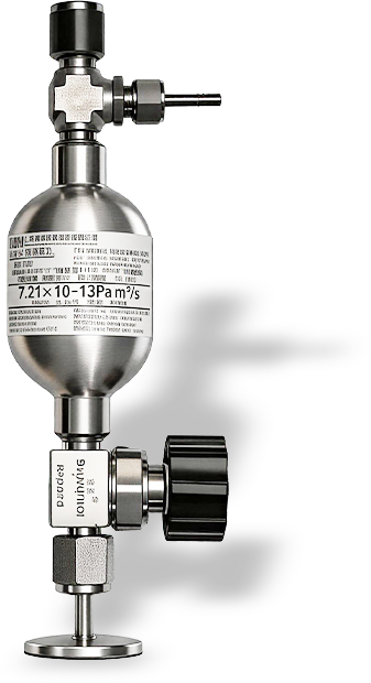
RMI-C12 Calibrated Leak Standards employ a single-channel capillary structure, with core components including the liquid reservoir, micro-channel capillary, PSOZV zero-dead-volume valve, and VCR fitting. The gas flow state within the capillary is determined by the Knudsen number (Kn):
$$Kn = \frac{\lambda}{D}$$
where $\lambda$ is the gas molecular mean free path and $D$ is the capillary diameter. When $Kn > 1$, the gas is in the molecular flow regime, and the leak rate $Q$ is proportional to the pressure difference:
where $L$ is the capillary length, $D$ is the diameter, $M$ is the molar mass of C$_{12}$H$_{26}$, $P_1$ is the inlet vapor pressure (~13 Pa), and $P_2$ is the outlet pressure (vacuum chamber, much less than $P_1$). The RMI-CAL algorithm automatically calculates the required $L$ and $D$ combination by constraining the target leak rate $Q$ and vapor pressure $P_1$, ensuring the capillary always operates in the molecular flow regime.
3.3 Gravimetric Calibration and SI Traceability Chain
RMI-C12 Calibrated Leak Standards employ the gravimetric method for calibration, which is directly traceable to the SI mass standard (kg) and time standard (s), making it one of the most direct and reliable leak rate calibration methods available.
where $\Delta m/\Delta t$ is the mass loss per unit time (measured by high-precision analytical balance), $R$ is the ideal gas constant, $T$ is the temperature, $M$ is the molar mass of C$_{12}$H$_{26}$, and $P_{std}$ is standard atmospheric pressure.
SI Traceability Chain
Gravimetric Method -> Analytical Balance (National Mass Standard) -> SI Unit System (kg, s) -> Leak Rate Q (Pa.m$^3$/s)
Every link in the traceability chain can be traced back to national metrology standards, ensuring the authority and international mutual recognition of the leak rate value. Calibration uncertainty: plus or minus 5% (k=2).
3.4 RGA Response Factor Definition and C12 Calibration Procedure
Residual Gas Analyzers (RGA) are typically factory-calibrated using only nitrogen or argon, leaving the hydrocarbon response factor unknown. This results in readings in "arbitrary units" (a.u.) that cannot be converted to absolute physical quantities. The core value of C12 Calibrated Leak Standards lies in establishing the RGA's absolute response factor for hydrocarbons.
The Response Factor (RF) is defined as the ratio of RGA ion current signal to known leak rate:
$$RF = \frac{I_{RGA}}{Q_{known}}$$
where $I_{RGA}$ is the ion current measured by RGA (A) and $Q_{known}$ is the known leak rate of the C12 calibrated leak (Pa.m$^3$/s). After RF calibration, any RGA reading can be converted to absolute flux:
$$Q_{actual} = \frac{I_{RGA}}{RF}$$
This conversion elevates the RGA from a "trend monitoring tool" to an "absolute metrology instrument" -- the core mechanism by which C12 Calibrated Leak Standards empower the semiconductor industry.
Standard Operating Procedure (SOP) for C12 Calibrated Leak RGA Calibration:
C12 Calibrated Leak RGA Calibration Procedure
Step
Operation
Details
Precautions
1
System preparation
Connect C12 leak to calibration chamber or target vacuum chamber via VCR fitting
Ensure all connections are leak-tight (He leak verification)
2
Pre-pump vacuum
Pre-pump leak line to below $10^{-2}$ Pa to exclude air and adsorbed gases
Pre-pump time greater than or equal to 30 minutes to ensure baseline stability
3
Open leak
Slowly open PSOZV valve, releasing C12 vapor to calibration chamber
Avoid rapid opening to prevent pressure surge
4
Signal stabilization
Wait for RGA reading to stabilize (m/z 43/57/71 peak area variation less than 2%)
Stabilization time typically 10-30 minutes
5
Data acquisition
Record RGA ion current I at each m/z channel and current C12 leak rate Q
Simultaneously record temperature for subsequent correction
6
RF calculation
Calculate response factor RF for each m/z channel per Equation (3-4)
Repeat 3 times and average; assess repeatability
7
Verification
Close C12 leak, confirm RGA signal returns to baseline level
If signal does not recover, check for system contamination
3.5 Cross-Tool Data Consistency Implementation Path
One of the core values of C12 Calibrated Leak Standards calibration is eliminating response differences between RGA systems on different tools, enabling cross-tool and cross-factory HHC data comparability. The implementation path is as follows:
Unified calibration source: All tool RGA systems within a fab use the same C12 calibrated leak standard for calibration.
Standardized SOP: Develop unified calibration operating procedures and data recording formats.
Database construction: Establish a central database of "Tool ID - RGA Model - RF Value - Calibration Date."
Deviation management: Set RF drift alarm thresholds (e.g., plus or minus 15%); exceeding limits requires investigation.
Through this path, "RGA reading of 500 on Tool A" and "RGA reading of 500 on Tool B" will represent the same physical flux, providing a reliable data foundation for process consistency management and AI predictive models.
The Essence of the Technological Leap
C12 Calibrated Leak Standards do not provide "more data" -- they provide "higher-quality data": data with physical dimensions, cross-platform comparability, and traceability to SI units. When the entire industry moves from "seeing a peak" to "knowing exactly how much," C12 Calibrated Leak Standards will become an indispensable metrological anchor.
Chapter 4 C12 in Full-Chain HHC/C Contamination Monitoring Scenarios
This chapter systematically analyzes nine core application scenarios for C12 Calibrated Leak Standards in semiconductor manufacturing equipment. Each scenario follows the logic of "problem definition -> C12 leak application value -> quantified benefit."
Problem definition: EUV lithography is extremely sensitive to HHC contamination. The 92 eV photons can break C-H/C-C bonds and initiate photochemical reactions; 0.1 nm of carbon deposition affects CD control. The industry currently relies on ellipsometry (result-oriented) and HRC cleaning (post-event remediation), lacking process-oriented absolute quantitative methods.
C12 leak application value -- three core scenarios:
Scenario A: RGA response factor calibration. Connect the C12 leak to the EUV chamber, release C12 vapor at known leak rate Q, record RGA response at m/z 43/57/71/170, and calculate RF = I/Q. Once the "RGA reading to absolute flux" conversion is established, real-time HHC level monitoring of the chamber becomes possible.
Scenario B: Photoresist outgassing rate quantitative certification. In an EUV simulated exposure chamber, use the C12-calibrated RGA to measure photoresist outgassing, outputting "X molecules/cm$^2$.s" rather than "Y arbitrary units." New photoresist batches can undergo absolute outgassing rate screening before fab entry, establishing dimensional qualified standards.
Scenario C: Cross-tool process consistency. Multiple EUV tool RGA systems within a fab are calibrated using the same C12 standard source, eliminating inter-tool response differences. This enables the transition from "fixed-cycle cleaning" to "condition-triggered cleaning," reducing unplanned downtime by 20% to 40%.
4.2 DUV Lithography: Scaled Calibration Market
Problem definition: DUV lithography equipment installed base is more than 10x that of EUV (thousands vs. hundreds of units), and domestic DUV is currently in rapid ramp-up. DUV scan exposure chambers and track units are equipped with RGA, but readings are not comparable across tools.
EUV vs. DUV Lithography Scenario Comparison
Comparison Dimension
EUV Lithography
DUV Lithography
Photon energy
92 eV (extreme ultraviolet)
6.4 eV at 193 nm
Carbon deposition mechanism
Photochemical reaction dominant
Physical adsorption plus weak photochemistry
Contamination severity
Extreme (0.1 nm affects yield)
Moderate (cumulative effect)
Equipment installed base
Hundreds (high-end lines)
Thousands (full-node coverage)
C12 leak entry point
Absolute quantification + predictive control
Standardized calibration + batch management
Market size assessment
Small but high unit value
Large and broad (broader market)
Strategic Assessment
DUV lithography represents the broader market for scaled C12 leak deployment. While the HHC issue on a single DUV tool is less severe than EUV, the DUV installed base is more than 10x larger. The value of C12 leaks in DUV -- "standardized calibration plus photoresist batch management" -- may be easier for customers to understand and accept than EUV's "absolute quantitative monitoring."
4.3 CVD/PECVD: Distinguishing Process Gas from Background Hydrocarbons
Problem definition: CVD equipment uses large quantities of organic precursors (TEOS, TMS, metal-organic compounds). Process gas and chamber background hydrocarbon mass spectral peaks overlap (e.g., m/z 43 appears in both process gas and residue), making it impossible to determine whether "the current reading comes from the process recipe or chamber contamination."
C12 leak application value:
RGA baseline calibration: After equipment maintenance, use C12 leak to verify RGA hydrocarbon response baseline, ensuring RGA reading drift is within controllable range.
Background recovery verification: After chamber cleaning, inject a known quantity of C12 vapor and compare theoretical vs. measured values to judge cleaning effectiveness -- establishing a quantitative "hydrocarbon residue index" metric.
Process gas purity cross-verification: When changing gas suppliers, use the C12-calibrated RGA to detect hydrocarbon impurities in the gas line.
Problem definition: After dry etching, chamber inner walls retain photoresist decomposition products (hydrocarbon polymers), affecting etch uniformity in subsequent batches. Traditional He leak detection can only detect physical leaks, not chemical residues.
C12 leak application value: Use the C12-calibrated RGA to scan the chamber before and after cleaning, establishing a "hydrocarbon residue index" quantitative model. Set quantitative thresholds -- e.g., "residue index less than $10^{12}$ molecules/cm$^2$" as the pass criterion. This enables a shift from "experience-based judgment" to "data-driven" clean quality control.
4.5 Ion Implanters: Ion Source Poisoning Prevention
Problem definition: Ion implanter ion sources (typically Freeman or Bernas type) are extremely sensitive to hydrocarbon contamination. Hydrocarbon molecules decompose in the high-temperature ion source, depositing on the filament and analyzer surfaces, causing beam current decay, emittance degradation, and even unplanned downtime.
C12 leak application value:
Ion source region hydrocarbon baseline quantification: Establish a quantitative model of "hydrocarbon partial pressure to ion source lifetime degradation."
Mass analyzer calibration: Verify resolution capability for light ion peaks such as m/z 12 (C$^+$) and m/z 13 (CH$^+$).
Preventive maintenance threshold setting: e.g., "C12-equivalent partial pressure greater than $10^{-8}$ Pa triggers early warning."
Quantified Benefit
A single preventive maintenance event can avoid 3-5 unplanned downtime incidents, delivering extremely high ROI. For an ion implanter valued at tens of millions of dollars, with each unplanned downtime costing hundreds of thousands of dollars, the C12 Calibrated Leak Standard investment payback period is typically less than 3 months.
Problem definition: Semiconductor materials (photoresist, O-rings, vacuum grease) must pass outgassing rate testing before fab entry. Existing TDS (Thermal Desorption Spectroscopy) can qualitatively analyze outgassing components but lacks quantitative precision; RGA dynamic testing cannot directly convert readings to outgassing rate.
C12 leak application value: Integrate C12 Calibrated Leak Standards into the material test chamber as an RGA calibration source, directly outputting "material outgassing rate = X Pa.m$^3$/s.g" or "Y molecules/s.cm$^2$" during testing. This provides fab customers with dimensional certification reports, enhancing material competitiveness. Enables transition from "black-box bidding" to "white-box grading."
Problem definition: FOUPs (Front Opening Unified Pods) are containers for wafer transport and temporary storage within the production line. FOUP bodies (PC, PBT materials) and internal seals slowly release hydrocarbons; residues from preceding processes accumulate inside the FOUP and affect subsequent processes. Currently there is almost no online monitoring, relying mainly on periodic replacement and AMC filters.
C12 leak application value: Use the C12-calibrated RGA in a FOUP test chamber to measure outgassing rates of different brands/batches of FOUPs, establishing a quantitative model of "FOUP outgassing rate to wafer surface organic growth," providing FOUP suppliers with dimensional quality certification data.
Problem definition: In e-beam inspection (eBeam Inspection) and CD-SEM equipment, high-energy electron beams (1-30 keV) strike the wafer surface causing photoresist/organic decomposition outgassing (EID, Electron-Induced Desorption), which deposits in the electron column and detector surfaces, causing image resolution degradation.
C12 leak application value: Use the C12-calibrated RGA to measure chamber hydrocarbon changes before and after e-beam irradiation, establishing a quantitative model of "e-beam dose to outgassing rate to chamber contamination rate," enabling differentiated pre-pump vacuum programs for different sample types.
4.9 Photomask Storage and Transfer Environment Monitoring
Problem definition: Both EUV and DUV photomasks have extremely high surface cleanliness requirements. Outgassing from the photomask pod (Pod) can deposit on the photomask surface; carbon growth on EUV photomasks changes reflectivity and affects exposure precision.
C12 leak application value: Configure C12-calibrated RGA in photomask storage cabinets (Stocker) and transfer chambers (Load Port), establishing a quantitative model of "storage environment hydrocarbon partial pressure to photomask surface carbon growth rate." This enables dynamic upper limits for photomask storage time (rather than fixed cycles), maximizing photomask utilization efficiency.
Scenario Value Assessment
The above nine scenarios can be categorized into four quadrants by "technical urgency x market size": High urgency + Large market: DUV lithography (scaled calibration), CVD/PECVD (process vs. background distinction) High urgency + Small market: EUV lithography (absolute quantification), ion implantation (ion source protection) Medium urgency + Large market: Etch equipment (clean verification), materials certification (outgassing testing) Medium urgency + Small market: FOUP storage, e-beam inspection, photomask storage
Chapter 5 Gaseous/Mixture Calibrated Leak Standards Across the Full Semiconductor Chain
Gaseous and mixture calibrated leak standards are the foundational tools for semiconductor RGA calibration, covering the full industry chain from equipment manufacturing acceptance, front-end wafer fabrication, materials incoming inspection, to back-end packaging and testing. This chapter systematically reviews the calibration requirements, usage methods, and problems solved at each stage, complementing Chapter 4 (C12 liquid-phase HHC/C contamination specific) to form a complete RGA calibration system.
5.1 Equipment Manufacturing and Factory Acceptance
Pre-delivery vacuum performance acceptance is the primary application scenario for RGA calibration. Every PVD, CVD, etch, or lithography tool must pass rigorous vacuum baseline testing and leak detector calibration before delivery to the fab.
He Calibrated Leak Standards -- Helium Mass Spectrometer Leak Detector (MSLD) Calibration. Chamber hermeticity verification relies on the helium mass spectrometer leak detector, whose sensitivity must be periodically calibrated using a He calibrated leak of known leak rate. RealMeter He leaks cover the $10^{-3}$ to $10^{-10}$ mbar.L/s range. Combined with the PSOZV zero-dead-volume valve design, online calibration can be completed without breaking the equipment vacuum -- the metrological foundation ensuring "zero leak" delivery.
Ar/N$_2$ Calibrated Leak Standards -- Pump Speed Verification. Through the Constant Flow Method, an Ar or N$_2$ leak of known leak rate is connected to the chamber, and the steady-state pressure is measured to calculate the effective pumping speed $S_{eff} = Q/P$. If the measured pumping speed deviates from the design value by more than 15%, it indicates blockage, leaks, or aging in the vacuum pump group or piping, which must be investigated and repaired before factory delivery.
H$_2$O Calibrated Leak Standards -- Water Vapor Response Calibration. Water vapor (m/z=18) in the equipment baseline is the most difficult to quantify and the most critical contaminant indicator. Using the H$_2$O leak to calibrate the RGA absolute sensitivity at m/z=17/18 establishes a quantitative chain of "water vapor partial pressure to ion current to equipment baseline assessment," ensuring the delivered equipment meets baseline water vapor level requirements.
RGA Calibration Requirements for Equipment Acceptance
Test Item
Leak Standard Used
Calibration Purpose
Problem Solved
Chamber hermeticity test
He leak ($10^{-4}$-$10^{-8}$ Pa.m$^3$/s)
Calibrate MSLD sensitivity
Ensure "zero leak" delivery
Pump speed verification
Ar/N$_2$ leak (known rate)
Calculate $S_{eff}$ via constant flow method
Verify vacuum pump group and piping performance
Baseline water vapor calibration
H$_2$O leak
Calibrate absolute sensitivity at m/z 17/18
Assess equipment baseline water vapor level
Cross-contamination isolation
Mixture leak (multi-component)
Verify gas delivery system isolation
Prevent cross-contamination between process gases
RGA full-range linearity
Kr/Xe/Ar mixture leak
Verify 2-140 amu range response
Ensure RGA full-system performance compliance
5.2 Front-End Wafer Fabrication (with C12 Anchor)
Front-end processes represent the most intensive and complex RGA calibration requirements. Chapter 4 (C12-specific) has analyzed organic quantitative calibration for HHC/C contamination in depth; this section focuses on inorganic gas calibration and vacuum environment monitoring using single-gas and mixture leak standards in these processes.
5.2.1 PVD Metal Deposition
PVD process chambers typically require baseline vacuum of $10^{-8}$-$10^{-9}$ mbar. Ar calibrated leak standards are used to calibrate RGA sensitivity at m/z=40, while C12 leaks calibrate the response at hydrocarbon characteristic peaks (m/z 43/57), enabling simultaneous quantitative monitoring of inorganic contaminants (Ar$^+$, N$_2^+$, O$_2^+$, H$_2$O$^+$) and organic contaminants (HHC fragments). Ar mixture leaks (e.g., H$_2$/He/N$_2$/Kr/Xe 1% each, balance Ar) can directly verify RGA multi-component trace detection capability in the Ar process atmosphere.
5.2.2 CVD/ALD
CVD and ALD use large quantities of organic precursors (TEOS, NH$_3$, WF$_6$, etc.); reaction gas residue and chamber cross-contamination are the primary risks. N$_2$/Ar leaks calibrate RGA sensitivity baselines for common inorganic background gases; H$_2$ leaks verify RGA response at m/z=2 in H$_2$ reduction processes (H$_2$ anneal, H$_2$ plasma treatment); mixture leaks (e.g., 1 ppm Xe in N$_2$) verify whether trace impurity residue levels in precursor-cleaned chambers meet specifications.
5.2.3 Plasma Etching
In etch processes, RGA endpoint detection relies on precise capture of reaction product concentration changes. Using CF$_4$ or SF$_6$ tracer gases at known leak rates (with Ar leak sensitivity calibration), the RGA response baseline at characteristic mass numbers (e.g., m/z=69 for CF$_3^+$) can be established. Mixture leaks (e.g., 1% Kr + 1% Xe, balance Ar) verify multi-component linearity retention in etch byproduct spectra.
5.2.4 Lithography (Including EUV)
The lithography chamber vacuum environment directly affects exposure uniformity and photoresist performance. Kr calibrated leaks calibrate RGA sensitivity at m/z=84 (Kr is used as purge/tracer gas in some lithography chambers); mixture leaks (1 ppm Xe in N$_2$ or H$_2$) verify residual Xe tracer levels after EUV optical chamber N$_2$ purge, ensuring purge efficiency and RGA monitoring accuracy.
5.2.5 Ion Implantation
Ion implanter high-vacuum chambers ($10^{-6}$-$10^{-7}$ mbar) require RGA real-time monitoring of trace impurities in the carrier gas (Ar or N$_2$). Ar leaks calibrate RGA sensitivity at m/z=40; He leaks verify chamber hermeticity and leak detector interlock response; mixture leaks (e.g., He/N$_2$/Ar/Kr/Xe 20% each) provide full-range mass discrimination effect calibration across 2-140 amu, ensuring accurate and reliable trace hydrocarbon monitoring in the ion source region.
5.2.6 Chamber Clean Verification
After periodic equipment maintenance, RGA must confirm the chamber has returned to baseline vacuum levels. Ar leaks establish the chamber normal baseline RGA fingerprint; after cleaning, compare the H$_2$O (m/z=18) peak decay curve and Kr/Xe mixture leak calibration response to determine whether the chamber is completely dry and ready for production. This is critical for shortening Wet-to-Dry Time and improving OEE.
5.3 High-Purity Materials Incoming Inspection and Gas Supply
High-purity gases and chemicals are the "food" of semiconductor manufacturing; their purity directly affects process yield. Gaseous and mixture calibrated leak standards play the "quality gatekeeper" role in the materials incoming inspection stage.
High-Purity Gas Impurity Verification. 6N+ grade high-purity Ar/N$_2$/H$_2$ from gas suppliers must have trace impurity (H$_2$O, O$_2$, CO, etc.) concentrations below 1 ppm. Using ppm-level mixture leaks (e.g., 1 ppm Kr/Xe in N$_2$) as RGA calibration input, a quantitative chain of "known 1 ppm to RGA reading to actual sample reading conversion" can be established, upgrading gas purity verification from a binary "pass/fail" judgment to a quantitative "specific impurity concentration value" report.
Gas Delivery Piping Monitoring. During long-distance gas transport from storage tanks to process chambers, piping adsorption/desorption behavior may introduce contamination. After full-range calibration using He/N$_2$/Ar/Kr/Xe 20% each mixture leak (Mixture 3), real-time monitoring at the piping end can detect abnormal drift at each mass number, rapidly locating contamination sources (pipe leaks, fitting outgassing, filter failure, etc.).
5.4 Back-End Packaging and Reliability Testing
Back-end packaging vacuum processes (vacuum reflow soldering, bonding) and hermetic packaging also require RGA calibration support.
Hermetic Package He Tracer Leak Testing. Power devices and MEMS devices must pass He tracer leak testing to verify hermeticity. Using large-leak-rate He calibrated leak standards ($10^{-4}$ Pa.m$^3$/s range) to calibrate sniffer-type He leak detectors ensures package cavity leak rates meet military standards (e.g., MIL-STD-833 requiring less than $5\times10^{-8}$ atm.cm$^3$/s).
Package Internal Atmosphere Analysis. After hermetic sealing, the internal fill gas (N$_2$ or H$_2$/N$_2$ mixture) purity must be verified by RGA. N$_2$ leaks calibrate RGA baseline sensitivity; H$_2$ leaks verify H$_2$/N$_2$ mixture atmosphere ratio accuracy; H$_2$O leaks calibrate m/z=18 response, ensuring no moisture penetration and no oxidation risk inside the package.
5.5 Failure Analysis and Quality Traceability
When wafer defects occur, RGA is an important tool for tracing contamination root causes. The accuracy of RGA calibration directly determines the credibility of failure analysis conclusions.
Defect Sample Chamber Gas Analysis. Place the defective sample in an RGA analysis chamber and release adsorbed gases through thermal desorption or e-beam bombardment. Pre-calibrate the RGA at m/z=40 and m/z=84 using Ar/Kr leaks to convert detected ion current to absolute flux, determining whether abnormal peaks originate from specific process gas residues (e.g., W isotope peaks from WF$_6$, characteristic Cl isotope ratio 3:1 from BCl$_3$, etc.).
Package Decap Internal Gas Analysis. After chemical decapsulation (Decap) of failed packages, use He leaks to calibrate RGA baseline response, H$_2$O leaks to verify moisture content, and C12 leaks for hydrocarbon calibration, comprehensively determining whether the failure was caused by moisture penetration (corrosion), organic contamination (electromigration), or gas impurity (oxidation).
5.6 Deep Application of Mixture Calibrated Leak Standards
Mixture calibrated leak standards are the most technologically sophisticated category in the RGA calibration system. They are not designed for "leak detection" but for precision quantitative capability building of the RGA. RealMeter mixture calibrated leak standards have three core applications:
5.6.1 Full-Range Uniform Sensitivity Scan
He/N$_2$/Ar/Kr/Xe 20% each mixture (Mixture 3) produces evenly distributed peaks on the RGA mass spectrum (m/z=2, 28, 40, 84, 132), covering the entire critical mass range of 2-140 amu. By comparing theoretical isotope ratios with actual measured ion current ratios, transmission efficiency correction factors at different mass numbers can be calculated, establishing a mass-number-to-sensitivity response curve. Without this correction, RGA sensitivity estimates at m/z=132 could be off by an order of magnitude.
5.6.2 Trace Detection Limit Verification (ppb to ppt)
1 ppm Kr in N$_2$ or 1 ppm Kr in H$_2$ mixture leaks, combined with appropriate leak rates and system pumping speeds, can achieve trace inputs from ppb to near-ppt levels in the test system:
By controlling leak rate and pump speed, Kr partial pressure inputs spanning 6 orders of magnitude from ppm to ppt can be achieved, providing traceable metrological means for RGA trace detection limit verification.
5.6.3 Isotope Abundance Calibration and High-End Metrological Transfer
Xe-132 ($\geq$94%)/Kr-84 ($\geq$56%)/Ar/N$_2$/He 20% each isotope mixture (Mixture 2) calibrates RGA resolution and quantitative accuracy for specific isotope abundances. This has irreplaceable value in nuclear industry, research facilities, and high-end semiconductor metrology -- it enables the RGA not only to "see" peaks at specific mass numbers but also to precisely determine their isotopic composition ratios.
Core Value Summary of Mixture Calibrated Leak Standards
Mixture calibrated leak standards are not "leaks with multiple gases mixed" -- they are "precision quantitative calibration sources embedded in real process atmospheres." 1 ppm Kr/H$_2$ produces approximately 10 ppb Kr partial pressure input in the H$_2$ process baseline, precisely matching the trace contamination monitoring requirements of 7 nm and below advanced processes -- enabling RGA calibration directly against actual process conditions, rather than performing unrealistic calibration in an "ideal vacuum."
Chapter 6 Synergistic Calibration System of Liquid-Medium Calibrated Leak Standards
Beyond the C12 core anchor, the RealMeter liquid-medium product line includes PFTBA and H$_2$O calibrated leak standards, forming a synergistic calibration system covering the full mass range and all contaminant types.
Technical Rationale for Product Selection
N-Tetradecane (C14, vapor pressure ~4 Pa) and n-hexadecane (C16, vapor pressure ~1 Pa) were excluded from the semiconductor RGA calibrated leak product line because their low vapor pressures make actual leak rates significantly affected by engineering factors such as connection piping length and interface temperature gradients, making repeatable and reliable calibration difficult. Dimethyl carbonate (DMC) was removed due to chemical instability of its ester functional group (susceptible to hydrolysis, low flash point), making it unsuitable as a precision calibration medium; DMC remains available for specific applications such as battery pack mass spectrometry direct testing.
6.1 PFTBA: Full-Range Calibration Gold Standard
Perfluorotributylamine (PFTBA, C$_{12}$F$_{27}$N) is the acknowledged "full-range calibration gold standard" in the mass spectrometry industry. Its fragment ions span the extremely wide mass range from m/z 69 to 671, enabling reliable RGA sensitivity calibration in the high mass-to-charge region above 200 amu. In the semiconductor field, PFTBA calibrated leak standards are primarily used for:
Verifying RGA response linearity in the m/z 170-671 range
Simulating RGA response characteristics of high-boiling-point vacuum pump oil vapors
Joint use with C12 to establish a full-spectrum sensitivity curve from m/z 43 to 671
6.2 H$_2$O Calibrated Leak Standards: Water Vapor Quantitative Calibration
Water vapor is the most common and difficult-to-quantify contaminant in semiconductor vacuum processes. The H$_2$O calibrated leak (m/z 17/18) is used to calibrate the RGA absolute response to water vapor, critical in the following scenarios: ALD process H$_2$O precursor residue monitoring (less than 0.1 ppb), chamber cleaning post-dry verification, and high-purity gas incoming moisture content inspection.
Three-Product Synergistic Positioning for Liquid-Medium Calibrated Leak Standards
C12 (N-Dodecane): HHC/C Contamination Absolute Quantification Core Anchor, m/z 43-170 PFTBA (Perfluorotributylamine): Full-Range Calibration Gold Standard, m/z 69-671 H$_2$O (Water): Water Vapor Quantitative Calibration Dedicated, m/z 17/18
These three products cover all critical mass ranges and contaminant types required for semiconductor RGA calibration, with neither redundancy nor gaps.
Chapter 7 Technical Boundaries and Unmet Scenarios
An honest presentation of technical boundaries is the mark of a responsible technical white paper. This chapter explicitly lists application scenarios that cannot be directly met by the current product portfolio and explains the fundamental reasons.
7.1 Reactive and Corrosive Process Gases
The following reactive/corrosive gases are extensively used in semiconductor CVD, etch, and ion implantation processes. Stable and reliable calibrated leak standards for these gases are currently unavailable worldwide:
Reactive/Corrosive Gases for Which Calibrated Leak Standards Are Not Available
Gas Type
Examples
Fundamental Reason Calibrated Leak Cannot Be Fabricated
Silicon source gases
SiH$_4$, Si$_2$H$_6$, TEOS
Flammable and explosive; thermal decomposition in micro-channels
Highly reactive with metal walls; WF$_6$ hydrolyzes to produce HF
Halogen-based etchants
Cl$_2$, HCl, BCl$_3$, CF$_4$, NF$_3$
Strongly corrosive; erodes micro-channel walls and sealing materials
Special fluorine-containing gases
HF, F$_2$
Extremely corrosive; reacts with virtually all metals
These limitations do not reflect RealMeter's insufficient technical capability but are determined by the inherent physicochemical properties of these gases. Even in the most developed calibrated leak markets (US, Europe, Japan), suppliers capable of stably providing reactive gas calibrated leak standards such as SiH$_4$, WF$_6$, and BCl$_3$ are extremely scarce or non-existent.
7.2 Applicability Boundary of Surrogate Gas Calibration
Surrogate gas calibration has very narrow applicability in semiconductor RGA applications. The identification of these gases often depends on their unique isotopic ratios (e.g., Cl 3:1, B 1:4) or characteristic fragmentation patterns, which surrogate gases cannot replicate. Surrogate gas calibration is a tactically usable but strategically unreliable transitional approach.
7.3 High/Low Temperature Variable-Condition Calibration
The current RealMeter product calibration temperature is 23 degree C (room temperature). Some semiconductor process chambers operate at temperatures significantly different from room temperature, requiring additional temperature correction models. The C12 leak temperature coefficient is approximately 12%/degree C; precision applications are advised to integrate temperature control modules (plus or minus 0.1 degree C) or develop temperature compensation algorithms.
Chapter 8 Alternative Strategies and Complementary Technologies
Faced with the technical boundaries described in Chapter 7, the semiconductor industry has developed a mature set of alternative strategies and complementary technology architectures.
Monitor vacuum baseline for silane residue (indirect)
WF$_6$/TMA/TiCl$_4$
Pressure monitoring + carrier flow + FTIR
Monitor carrier gas abnormal peaks to infer source leaks
Cl$_2$/HCl/BCl$_3$
Electrochemical sensors, OES
Monitor chamber baseline; indirect verification via characteristic peaks
NF$_3$/CF$_4$/SF$_6$
Infrared spectroscopy, OES endpoint detection
Post-clean residue verification
8.2 RGA Indirect Inference Strategies
When direct calibration of target gases is not possible, RGA employs three indirect monitoring strategies: correlated parameter monitoring (inferring main process state through carrier gas anomalies and byproduct concentration changes), fragmentation pattern library comparison (establishing a "normal process" full-spectrum fingerprint library and triggering alarms on spectral deviation), and process window verification (multi-sensor joint acquisition to establish statistical correlations, with RGA maintaining the verified window during production).
8.3 Best Practices for In-Situ Calibration
Recalibrate sensitivity factors every 3-6 months; prioritize in-situ calibration at actual process chamber locations; maintain stable ambient temperature during calibration (less than 1 degree C/hour variation); periodically use C12 leaks for full-range linearity checks; for RGA systems monitoring organic contaminants, perform high mass-to-charge region calibration with C12 at least every 6 months.
Chapter 9 Technical Significance and Strategic Value
9.1 Fab Data Asset Accumulation and AI Readiness
One of a wafer fab's core competitive advantages is the completeness and quality of its process database. C12 leak-calibrated RGA data offers three unique values:
Unified dimensions: Enables HHC data comparability across different fabs and different tools, breaking down "data silos." C12-calibrated RGA outputs in units of molecules/cm$^2$.s or Pa.m$^3$/s are absolute quantities that can directly participate in physical calculations.
Process knowledge preservation: Knowledge loss from engineer turnover can be mitigated through "dimensional standard operating procedures" (SOP) -- new engineers need only execute standardized C12 calibration workflows to obtain reliable data.
AI readiness: Absolute quantitative data can be directly fed into machine learning models to train predictive models of "HHC flux to carbon deposition rate to CD deviation to yield loss." In the context of smart manufacturing and Industry 4.0, "data quality" determines the "AI ceiling."
9.2 Differentiated Competitiveness for Domestic Semiconductor Equipment
Domestic semiconductor equipment is at a critical juncture of evolving from "usable" to "excellent." C12 leak calibration capability provides domestic equipment manufacturers with a differentiated competitive dimension:
Domestic Equipment Differentiated Competitiveness: Traditional Path vs. C12-Enabled Path
"Metrological traceability capability" may become an asymmetric advantage -- not doing better on a mature metric, but establishing new standards in dimensions the competition has not yet emphasized.
9.3 Strategic Leap from "Catch-Up" to "Standard Definition"
China's semiconductor industry has long faced the "latecomer's dilemma" -- optimizing within a standard framework defined by others makes true超越 difficult. C12 Calibrated Leak Standards and the associated RGA absolute calibration methodology provide an opportunity to "define new standards":
Technology leadership: Chinese enterprises have taken the international lead in C12 leak engineering applications, with hundred-unit-scale deployment experience accumulating valuable real-world data.
Standard setting: Collaborate with the National Institute of Metrology to drive national metrology standards development and participate in SEMI standards working groups to transform practical experience into industry standards.
Ecosystem building: Establish modular "C12 leak + RGA + temperature control" calibration subsystems to lower integration barriers and expand the application ecosystem.
Strategic Assessment
At the critical stage where China's semiconductor industry is transitioning from "catch-up" to "parallel-run" and even "leadership," technologies that "define new standards" may be more strategically valuable than technologies that "optimize old metrics." C12 Calibrated Leak Standards and the RGA absolute calibration methodology are precisely such "new-standard-defining" technologies.
Start from domestic production lines; use data to prove absolute quantification value for yield improvement
10.3 Future Development Trends
Short-term (1-2 years): Promote using established domestic equipment manufacturers as benchmarks to other domestic equipment makers; focus on DUV lithography, CVD/PECVD, and ion implanter as the three primary scenarios; launch FOUP outgassing rate standardization testing pilots; accumulate response factor databases across different equipment models and process conditions.
Mid-term (3-5 years): Extend from "equipment factory calibration" to "fab production line online calibration," achieving full-lifecycle metrological coverage; jointly establish "absolute outgassing rate certification system" with photoresist manufacturers; explore "Calibration-as-a-Service" (CaaS) business models; DUV scaled application feeds back to mature EUV technology.
Long-term (5+ years): If the domestic EUV mass production timeline is realized, C12 leaks are expected to become the de facto standard configuration for EUV vacuum systems; drive SEMI/national standards to incorporate "hydrocarbon RGA absolute calibration" into equipment acceptance specifications; expand from "semiconductor-specific tool" to "universal vacuum domain standard source" (aerospace, nuclear industry, research facilities).
Conclusion
This white paper has systematically presented the RealMeter C12 n-dodecane Calibrated Leak Standard as the core anchor of a comprehensive semiconductor RGA calibration system. The core conclusions are as follows:
First, the industry pain point is clear. As advanced processes evolve to 7 nm and below, EUV lithography and other equipment have seen dramatically increased sensitivity to HHC contamination. The current "black-box" monitoring model of ellipsometer + HRC + RGA lacks process-oriented absolute quantitative capability, and the industry urgently needs to leap from "semi-qualitative trend monitoring" to "absolute quantitative metrology."
Second, C12's technical positioning is precise. N-Dodecane (C$_{12}$H$_{26}$), with its moderate vapor pressure (~13 Pa), rich mass spectral features (m/z 43-170), high chemical stability, and SI-traceable gravimetric calibration, is the ideal anchor substance for RGA to advance from semi-quantitative to absolute metrology. DMC and other liquid-phase media cannot replace C12 in the core position of HHC absolute quantification.
Third, application scenario coverage is comprehensive. C12 Calibrated Leak Standards cover nine core application scenarios in semiconductor manufacturing -- EUV lithography absolute quantification, DUV lithography scaled calibration, CVD/PECVD process vs. background distinction, etch clean verification, ion implanter ion source protection, materials certification outgassing testing, FOUP outgassing rate standardization, e-beam inspection EID characterization, and photomask storage environment monitoring -- with a clear value gradient.
Fourth, the commercialization foundation is established. Hundred-unit-scale procurement and deployment has been realized, covering DUV, EUV, CVD, and etch platforms. The four-phase implementation strategy (research to equipment maker to fab to standard) is clearly feasible.
Fifth, the strategic significance is profound. C12 Calibrated Leak Standards and the RGA absolute calibration methodology provide domestic semiconductor equipment with an opportunity to "define new standards." At the critical stage of transitioning from "catch-up" to "leadership," "metrological traceability capability" may become an asymmetric competitive advantage.
Semiconductor manufacturing is entering a new stage that requires "absolute quantification." C12 Calibrated Leak Standards provide not more data, but higher-quality data -- data with physical dimensions, cross-platform comparability, and traceability to SI units. Such data is the foundation for building process models, training AI algorithms, and achieving predictive maintenance. When the entire industry moves from "seeing a peak" to "knowing exactly how much," C12 Calibrated Leak Standards will become an indispensable metrological anchor.
References
Baji, S., et al. (2020). Carbon contamination of EUV optics: Fundamentals and mitigation. Journal of Vacuum Science & Technology B, 38(6), 062602.
Kanjilal, D., et al. (2019). Carbon growth on EUV multilayer optics: Mechanisms and cleaning strategies. Proceedings of SPIE, 11177, 111770P.
ISO 20485:2017, Non-destructive testing -- Calibration of leak artifacts of known leak rate. International Organization for Standardization, Geneva, Switzerland.
Setina, J. (1999). New practical reference leak with a glass permeation element. Vacuum, 53(1-2), 137-141.
Lafferty, J. M. (1972). Review of physical principles underlying the atomistic generation of calibration leaks. Journal of Vacuum Science and Technology, 9(4), 1222-1226.
O'Hanlon, J. F. (2003). A User's Guide to Vacuum Technology (3rd ed.). John Wiley & Sons.
SEMI E52-1216, Practice for referencing mass flow controller output to volumetric flow rates. SEMI Standards.
National Institute of Standards and Technology (NIST), Leak Calibration Services, NIST Special Publication 250-XX.
Werutsky, M., et al. (2024). History of Residual Gas Analysis (RGA) in Industry and Its Way to the Age of Industry 4.0. Vacuum, 224, 113193.
Stanford Research Systems. RGA Application Note: Quantitative Analysis with the RGA. SRS Technical Library, 2005.


 About RealMeter上海睿米仪器仪表(RealMeter)


 办公电话:021-5822 0307
 技术支持:13601764364(微信同号)
 企业官网:www.realmeter.cc
 官方邮箱:contact@realmeter.cn
 公司地址:上海浦东新区航头镇乐城路30弄4号